
Page 35 - Demo
P. 35
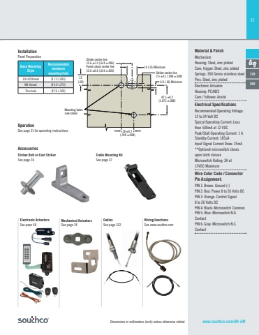
33Dimensions in millimeters (inch) unless otherwise statedOperationSee page 21 for operating instructionsCable Mounting Kit See page 37Mechanical ActuatorsSee page 34CablesSee page 322Wiring/JunctionsSee www.southco.comElectronic ActuatorsSee page 48Striker Bolt or Cast StrikerSee page 36AccessoriesMaterial & FinishMechanismHousing: Steel, zinc platedCam, trigger: Steel, zinc platedSprings: 300 Series stainless steelPins: Steel, zinc platedElectronic Actuator:Housing: PC/ABS Cam / follower: AcetalElectrical Specifi cationsRecommended Operating Voltage: 12 to 24 Volt DCTypical Operating Current: Less than 500mA at 12 VDCPeak/Stall Operating Current: 1 AStandby Current: 185uAInput Signal Current Dra 25mA**Optional microswitch closes upon latch closureMicroswitch Rating: 3A at 12VDC MaximumWire Color Code / Connector Pin Assignment:PIN 1: Brown: Ground (-)PIN 2: Red: Power 8 to 26 Volts DCPIN 3: Orange: Control Signal 8 to 26 Volts DCPIN 4: Black: Microswitch CommonPIN 5: Blue: Microswitch N.O. ContactPIN 6: Grey: Microswitch N.C. Contact12V24V14 (.55) Minimum4.0 (.16) MinimumStriker center line2.5 ±0.1 (.098 ±.004)Striker center line15.6 ±1.2 (.614 ±.046)Panel cutout center line15.6 ±0.5 (.614 ±.020)42.5 ±0.2(1.673 ±.008)18 ±0.2 (.709 ±.008)15(.59)Mounting holes(see table)Base Mounting StyleRecommendedminimummounting hole1/4-20 thread Ø 7.2 (.283)M6 thread Ø 6.9 (.272)Thru hole Ø 7.6 (.300)InstallationPanel Preparationwww.southco.com/R4-EM
