
Page 29 - Demo
P. 29
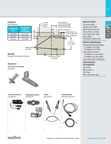
27Dimensions in millimeters (inch) unless otherwise statedOperationSee page 21 for operating instructionsStriker Bolt or Cast StrikerSee page 36AccessoriesBase Mounting StyleRecommendedminimummounting hole1/4-20 thread Ø 7.2 (.283)M6 thread Ø 6.9 (.272)Thru hole Ø 7.6 (.300)Material & FinishTop housing: Nylon Gearbox cover: PC/ABSBottom housing, Pivot pins, Screws: Steel, zinc platedCam, Trigger: Steel, sealedGears: AcetalPin, Springs: Stainless steelElectrical Specifi cationsRecommended Operating Voltage: 12 V Models: 8 to 14 VDC 24 V Models: 21 to 26 VDCTypical Operating Current : 12 V Models: Less than 200mA 24 V Models: Less than 100mALatch status switch: 1A MaximumLatch Connector Pin AssignmentPIN 1: PowerPIN 2: Ground (-)PIN 3: NonePIN 4: Latch status signal14 (.55) Minimum5 (.197) Minimum42.5 ±0.2(1.673 ±.008)18 ±0.2 (.709 ±.008)15(.59)28(1.10)ExtendedhousingversionMounting holes(see table)Striker center line15.6 ±1.2 (.614 ±.046)Panel cutout center line15.6 ±0.5 (.614 ±.020)Striker center line2.5 ±0.1 (.098 ±.004)12V24VMechanical ActuatorsSee page 34CablesSee page 322Wiring/JunctionsSee www.southco.comElectronic ActuatorsSee page 48www.southco.com/R4-EMInstallationPanel Preparation
