
Page 33 - Demo
P. 33
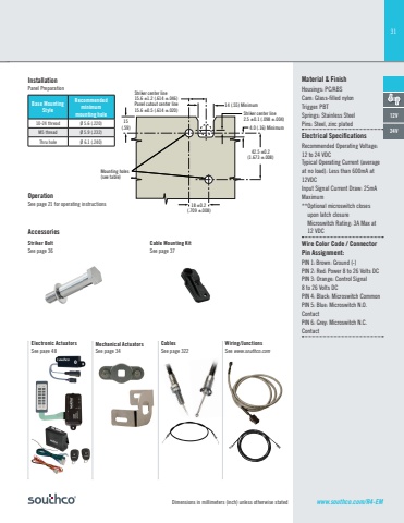
31Dimensions in millimeters (inch) unless otherwise statedOperationSee page 21 for operating instructionsAccessoriesStriker BoltSee page 36Cable Mounting KitSee page 37Base Mounting StyleRecommendedminimummounting hole10-24 thread Ø 5.6 (.220)M5 thread Ø 5.9 (.232)Thru hole Ø 6.1 (.240)InstallationPanel PreparationMaterial & FinishHousings: PC/ABSCam: Glass-fi lled nylonTrigger: PBTSprings: Stainless SteelPins: Steel, zinc platedElectrical Specifi cationsRecommended Operating Voltage: 12 to 24 VDCTypical Operating Current (average at no load): Less than 600mA at 12VDCInput Signal Current Dra 25mA Maximum ** Optional microswitch closes upon latch closureMicroswitch Rating: 3A Max at 12 VDCWire Color Code / Connector Pin Assignment:PIN 1: Brown: Ground (-)PIN 2: Red: Power 8 to 26 Volts DCPIN 3: Orange: Control Signal 8 to 26 Volts DCPIN 4: Black: Microswitch CommonPIN 5: Blue: Microswitch N.O. ContactPIN 6: Grey: Microswitch N.C. Contact12V24V14 (.55) Minimum4.0 (.16) MinimumStriker center line2.5 ±0.1 (.098 ±.004)Striker center line15.6 ±1.2 (.614 ±.046)Panel cutout center line15.6 ±0.5 (.614 ±.020)42.5 ±0.2(1.673 ±.008)18 ±0.2 (.709 ±.008)15(.59)Mounting holes(see table)Mechanical ActuatorsSee page 34CablesSee page 322Wiring/JunctionsSee www.southco.comElectronic ActuatorsSee page 48www.southco.com/R4-EM
