
Page 30 - Demo
P. 30
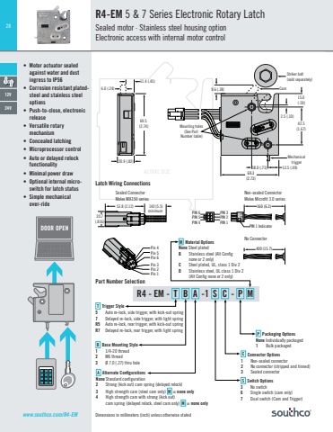
28www.southco.com/R4-EM Dimensions in millimeters (inch) unless otherwise statedR4 - EM - T B A -1 S C - P M53.8 (2.12) 140 (5.5)minimum 69.5 (2.74)20.9 (.82)9.6 (.38)2.5 (.10)15.0(.59)42.5(1.67)Striker bolt(sold separately)Cam69.3(2.73)12.5 (.49)Mounting holes(See Part Number table)Mechanicaltrigger18.0 (.71)16.09.5 (.37) (.63)5.9 (.23)12.15 (.48)6.0 (.24)11.4 (.45) 430 (16.9)Pin 4Pin 5Pin 6Pin 3Pin 2Pin 1Pin 6Pin 5Pin 4Pin 1Pin 2Pin 3Ø3.28 (.129) accessory mounting holes x 2 Max. insertion depth 5mmØ3.28 (.129) accesory mounting holes x 2 Max. insertion depth 5mm16.09.5 (.37) (.63)5.9 (.23)12.15 (.48)5.9 (.23)Mechanical triggerMechanical over-ride cable mounting bracket kit for rear trigger latch (R4-EM-87).(See page XXX)3 (.12) 39.68 (1.56)16.76 (.66)12.7 (.50) HexØ 25.4 (1.00) Ø 9.5(.37)7.5(.30)WasherO-RingM8 x 1.25Thread38.1(1.50)27.7(1.09)25.4(1.00) 2.8(0.11)20.7(.816)ACTUAL SIZENo ConnectorNon-sealed ConnectorMolex Microfit 3.0 seriesSealed ConnectorMolex MX150 seriesPart Number SelectionP Packaging OptionsNone Individually packaged1 Bulk packagedC Connector Options1 Non-sealed connector2 No connector (stripped and tinned)3 Sealed connectorS Switch Options3 No switch6 Single switch (cam only)7 Dual switch (Cam and Trigger)A Alternate ConfigurationsNone Standard configuration2 Strong (kick out) cam spring (delayed relock)3 High strength cam (steel cam only) M = none only4 High strength cam with strong (kick out)cam spring (delayed relock, steel cam only) M = none onlyB Base Mounting Style1 1/4-20 thread2 M6 thread3 Ø 7.0 (.27) thru holeT Trigger Style5 Auto re-lock, side trigger, with kick-out spring7 Delayed re-lock, side trigger, with light springR5 Auto re-lock, rear trigger, with kick-out springR7 Delayed re-lock, rear trigger, with light springM Material OptionsNone Steel platedB Stainless steel (Alt Confignone or 2 only)C Steel plated, UL, class 1 Div 2D Stainless steel, UL class 1 Div 2 (Alt Config none or 2 only)160 (6.3)11 2 3PIN 3PIN 2PIN 1PIN 1 IndicatorPIN 6PIN 5PIN 4 400 (15.7)160 (6.3)11 2 3PIN 3PIN 2PIN 1PIN 1 IndicatorPIN 6PIN 5PIN 4 400 (15.7)Latch Wiring Connections53.8 (2.12) 140 (5.5)minimum 69.5 (2.74)20.9 (.82)9.6 (.38)2.5 (.10)15.0(.59)42.5(1.67)Striker bolt(sold separately)Cam69.3(2.73)12.5 (.49)Mounting holes(See Part Number table)Mechanicaltrigger18.0 (.71)16.09.5 (.37) (.63)5.9 (.23)12.15 (.48)6.0 (.24)11.4 (.45) 430 (16.9)Pin 4Pin 5Pin 6Pin 3Pin 2Pin 1Pin 6Pin 5Pin 4Pin 1Pin 2Pin 3Ø3.28 (.129) accessory mounting holes x 2 Max. insertion depth 5mmØ3.28 (.129) accesory mounting holes x 2 Max. insertion depth 5mm16.09.5 (.37) (.63)5.9 (.23)12.15 (.48)5.9 (.23)Mechanical triggerMechanical over-ride cable mounting bracket kit for rear trigger latch (R4-EM-87).(See page XXX)3 (.12) 39.68 (1.56)16.76 (.66)12.7 (.50) HexØ 25.4 (1.00) Ø 9.5(.37)7.5(.30)WasherO-RingM8 x 1.25Thread38.1(1.50)27.7(1.09)25.4(1.00) 2.8(0.11)20.7(.816)R4-EM 5 & 7 Series Electronic Rotary LatchSealed motor · Stainless steel housing optionElectronic access with internal motor control• Motor actuator sealed against water and dust ingress to IP56• Corrosion resistant platedsteel and stainless steel options• Push-to-close, electronic release• Versatile rotary mechanism• Concealed latching• Microprocessor control• Auto or delayed relock functionality• Minimal power draw• Optional internal microswitch for latch status• Simple mechanical over-ride12V24VDOOR OPEN1 2 34 5 67 8 9 0 #
