
Page 31 - Demo
P. 31
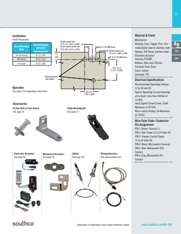
29Dimensions in millimeters (inch) unless otherwise stated www.southco.com/R4-EM14 (.55) Minimum4.0 (.16) MinimumStriker center line2.5 ±0.1 (.098 ±.004)Striker center line15.6 ±1.2 (.614 ±.046)Panel cutout center line15.6 ±0.5 (.614 ±.020)42.5 ±0.2(1.673 ±.008)18 ±0.2 (.709 ±.008)15(.59)Mounting holes(see table)OperationSee page 21 for operating instructionsCable Mounting KitSee page 37Base Mounting StyleRecommendedminimummounting hole1/4-20 thread Ø 7.2 (.283)M6 thread Ø 6.9 (.272)Thru hole Ø 7.6 (.300)InstallationPanel PreparationStriker Bolt or Cast StrikerSee page 36AccessoriesMaterial & FinishMechanismHousing, Cam, Trigger, Pins: Zinc nickel plated steel or stainless steelSprings: 300 Series stainless steelElectronic ActuatorHousing: PC/ABSBellows, Wire seal: SiliconePerimeter Seal: BunaCams: AcetalGrommet: TPEElectrical Specifi cationsRecommended Operating Voltage: 12 to 24 Volt DCTypical Operating Current (average at no load): Less then 600mA at 12 VDCInput Signal Current Dra 25mA Maximum at 24 VDCMicro-switch Rating: 3A Maximum at 12VDCWire Color Code / Connector Pin Assignment:PIN 1: Brown: Ground (-)PIN 2: Red: Power 12 to 24 Volts DCPIN 3: Orange: Control Signal 12 to 24 Volts DCPIN 4: Black: Microswitch CommonPIN 5: Blue: Microswitch N.O. ContactPIN 6: Grey: Microswitch N.C. Contact12V24VMechanical ActuatorsSee page 34CablesSee page 322Wiring/JunctionsSee www.southco.comElectronic ActuatorsSee page 48
