
Page 238 - Demo
P. 238
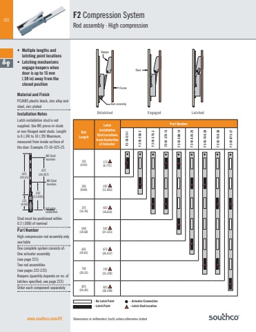
222Dimensions in millimeters (inch) unless otherwise statedF2 Compression SystemRod assembly · High compressionwww.southco.com/F2• Multiple lengths and latching point locations• Latching mechanisms engage keepers when door is up to 15 mm (.59 in) away from the closed positionMaterial and FinishPC/ABS plastic black, zinc alloy and steel, zinc platedInstallation NotesLatch installation stud is not supplied. Use M5 press-in studs or non-flanged weld studs. Length is 6 (.24) to 10 (.39) Maximum, measured from inside surface of the door. Example: F2-10-625-25Stud must be positioned within 0.2 (.008) of nominalPart NumberHigh compression rod assembly only see tableOne complete system consists of:One actuator assembly (see page 221)Two rod assemblies (see pages 222-223) Keepers (quantity depends on no. of latches specified; see page 223)Order each component separately625(24.61)672(26.457)297(11.693)125(4.92)ActuatorcenterlineM5 StudlocationM5 Stud location - No Latch Point - Actuator Connection - Latch Point - Latch Stud Location Unlatched Engaged LatchedRodLengthLatchInstallation Stud Locationsfrom Centerline of ActuatorPart NumberF2-10-125-1F2-10-250-2F2-10-375-3F2-10-375-13F2-10-500-14F2-10-625-25F2-10-750-26F2-10-750-36F2-10-875-37125(4.92)172 (6.772)250(9.84) 297 (11.693)375(14.76)422 (16.614)500(19.69)547 (21.535)625(24.61)672 (26.457)750(29.53)797 (31.378)875(34.45)922 (36.299)DoorFrameKeeperRod assemby
