
Page 266 - Demo
P. 266
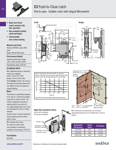
Dimensions in millimeters (inch) unless otherwise stated242www.southco.com/C3ACTUAL SIZEApproximate Pull-Up ForceSpring Colour Part Number13 N (3 lbf) Blue C3-180322 N (5 lbf) Silver C3-180544 N (10 lbf) Black C3-1810CommonConnection is live when latch is closedConnection is live when latch is open Two holes Ø 3.3 (.130 ) for M3 or No. 4 sizescrews or Ø 3 rivets+.004- 0 +0.1- 0 40.6(1.60 )+0.3- 0+.012- 00±0.2(0±.008)Centerline of frame holes 15.7 (.618 ) or for adjustability 24.7 (.972 ) (see note)+0.1- 0+.004- 0 +0- 0.3 +0- .012FrameØ4.3 (.169 ) 2 x holes for M4 or No.8 size screws +0.1- 0 +.004- 055±0.5(2.165±.020)Centerline of door holes Door 7(.276 )+0- 0.3+.0- .012Volts DC61 .75.5.250 25 50 75 125 250Current DC (amps)Over 50 V DC, inductive loads should be greatly reducedSwitch specification. Subminiature VDE, UL approved. Switch is fitted with fast-on terminals. Max AC voltage 250V, max AC current 6A. See graph below for DC resistive load.2.5(.1)7.9(.31)2.8 (.11)6.4(.25)8.7(.34)7(.28)7(.28)3 x 0.5(.02)1.7(.07)48.5(1.90)13.7(.54)39.4(1.55)40.6(1.60)5.3 (.21)3.8 (.15) 2 x Ø 3.3 (.13) 2 x 3.3 (.13) 5.1(.20) 14.5 (.57)Cam8 (.32)28(1.11)22.5(.89)THIS PRODUCT IS SPECIFICALLY DESIGNED TO BE USED AS A MECHANICAL GRABBER CATCH WITH AN ELECTRIC SWITCH. THE SWITCH IS DESIGNED TO OPERATE AN INDICATOR LIGHT OR FORM PART OF A NON-SAFETY RELATED LOGIC CIRCUIT. NOT DESIGNED FOR USE AS A SAFETY INTERLOCK.TERMINAL COVER IS USED FOR PROTECTION DURING SHIPPING ONLY. USE STRAIN RELIEF ON WIRES.Terminal detail4(.16)4(.16)55(2.17)Orientationindicator4.3(.17)23.8(.94)4 (.16)11.5(.45)72(2.83)Catch KeeperNote: These holes and dimensions are used only if adjustability through the use of slotted holes in catch is desired.Right Side Installation ShownInvert catch and keeper for left side installationC3 Push-to-Close LatchPull-to-open · Grabber catch with integral Microswitch • Opens and closes switch contacts with door operation• One assembly includes catch and keeper• Spring loaded over-center latchingMaterial and FinishHousing: PC/ABS or glass-filled nylonKeeper: Mineral filled nylonPerformance Details Operating temperature range:-40ºC (-40ºF) to 60ºC (140ºF)Flammability rating: UL94-V0Installation NotesMax. tightening torque on mounting screws (not supplied):Catch 1.1 Nm (9.7 inlbf) Keeper 2.8 Nm (24.8 inlbf)Orient keeper to latch. The arrow on the keeper should point towards the cam. Mount to door and adjust for smooth latching.NotesThis product is specifically designed to be used as a mechanical grabber catch with an electric switch. The switch is designed to operate an indicator light or form part of a non-safety related logic circuit. This is not designed for use as a safety interlock.Terminal cover is used for protection during shipping only. Use strain relief on wires.Min. distance from frame(or surface on which catchsub-assembly is mounted) to centerline of door hinge is 150 (5.9)Part NumberSee table
