
Page 224 - Demo
P. 224
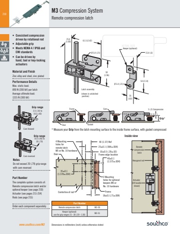
210ACTUAL SIZEPart NumberRemote compression latch M3-50Keeper (optional)use for grip ranges 15 - 30 (.59 - 1.18) M3-51Inside viewwww.southco.com/M3 Dimensions in millimeters (inch) unless otherwise statedM3 Compression SystemRemote compression latchGasketFrameDoor5 (.2) Compression CamGrip*Latch assemblyKeeper (optional)15.4 (.6) (shown in unlatched position)25.4(1.00) 61.5 (2.42)50(1.96)54 (2.14)16(.63)Ø 5.4 (.21)Ø 5.4 (.21)Cam forwardGrip range3.5 (.14) to10.2 (.40)Cam reversedGrip range10.2 (.40) to20 (.79)35±0.1(1.378±.004)40 (1.57) Ref25±0.1 (.984±.004)18±0.1 (.71±.004)40±0.1(1.575±.004)2 Mounting holes for optional keepers M5 or No. 10 hardware4 Mounting holes for remote latch M5 or No. 10 hardwareCenterline of rod FrameDoor10±0.5 (.39±.02) Frame edge location * Measure your Grip from the latch mounting surface to the inside frame surface, with gasket compressed• Consistent compression driven by rotational rod• Adjustable grip• Meets NEMA 4 / IP66 and EMI standards• Can be driven by hand, tool or key-locking actuatorsMaterial and FinishZinc alloy and steel, zinc platedPerformance DetailsMax. static load: 890 N (200 lbf) per latchAverage ultimate load:1335 N (300 lbf)NotesDo not exceed 20 (.79) grip range with cam reversedPart NumberThe complete system consists of: Remote compression latch and/or optional keeper (see page 210)Actuator (see pages 211-214)Rods (see page 215)Order each component separatelyRemote compression latchHexagonal rodActuator (lift handle shown)
