
Page 599 - Demo
P. 599
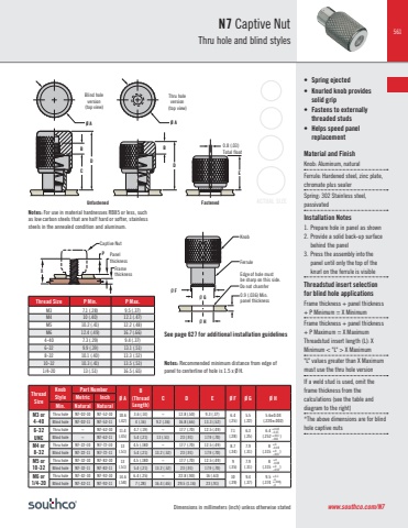
541Dimensions in millimeters (inch) unless otherwise stated6-32 Thread SizeInstallationStyleOuter Panel DimensionsBPart Number Screw Projection Beyond Outer Surface of PanelKnob Height%u2020TotalFloatPanel PreparationA Min. A Max. Phillips / SlotCombinationTORX%u00ae / SlotCombination P-1 P-2 H-1 H-2 F* %u00d8 D %u00d8 ZPress-InStyle0.9%u2020 (.036) ~ ~ 4C-PS-06-1P0-K000 4C-TS-06-1P0-K000 0.7 (.03) 5 (.20) 15.5(.61)11.3(.44)0.7(.03) 6.4 (.250 ) 3.7 (.146 ) 4C-PS-06-2P0-K000 4C-TS-06-2P0-K000 2.3 (.09) 6.6 (.26)0.8 (.031)1.6 (.063) ~ 4C-AB-P-0740-K000 4C-BB-P-0740-K000 0.7 (.03)4 (.16) 14.6 (.57) 5.8 (.228 ) 3.7 (.146 ) 4C-AB-P-0750-K000 4C-BB-P-0750-K000 5 (.20) 15.6 (.61) 4C-AB-P-0760-K000 4C-BB-P-0760-K000 6 (.24) 16.6 (.65) 4C-AB-P-0770-K000 4C-BB-P-0770-K000 7 (.28) 17.6 (.69) 4C-AB-P-0740-W000 4C-BB-P-0740-W000 4 (.16) 14.6 (.57) 4C-AB-P-0750-W000 4C-BB-P-0750-W000 5 (.20) 15.6 (.61)P.C. BoardStyle1.5 (.06) ~ ~ 4C-PS-06-1B0-K000 4C-TS-06-1B0-K000 1.7 (.07) 6.2 (.25) 14.5(.57)10 (.39) 6.4 %u00b1 0.1 (.252 %u00b1 .004) 3.7 (.146 )Flare-InStyle1.5 (.059)3.2 (.125)0.4 (.016)4C-PS-06-1F1-K000 4C-TS-06-1F1-K000 0.8 (.03) 5 (.20) 15.5(.61)11.3(.44) 5.4 (.213 ) 3.7 (.146 )4C-PS-06-2F1-K000 4C-TS-06-2F1-K000 2.3 (.09) 6.6 (.26)0.8 (.031)1.6 (.063)0.2 (.008) 4C-AB-F-0740-K000 4C-BB-F-0740-K001 0.7 (.03)4 (.16) 14.6 (.57) 4C-AB-F-0750-K000 4C-BB-F-0750-K000 5 (.20) 15.6 (.61) 4C-AB-F-0760-K000 4C-BB-F-0760-K000 6 (.24) 16.6 (.65) 4C-AB-F-0770-K000 4C-BB-F-0770-K000 7 (.28) 17.6 (.69) 4C-AB-F-0740-W000 4C-BB-F-0740-W000 4 (.16) 14.6 (.57) 4C-AB-F-0750-W000 4C-BB-F-0750-W000 5 (.20) 15.6 (.61)(shown in table)10-32 Thread SizeInstallationStyleOuter Panel Dimensions B LPart Number Screw Projection Beyond Outer Surface of PanelKnob Height%u2020TotalFloatPanel PreparationAMin.A Max.Phillips / SlotCombinationTORX%u00ae / SlotCombination P-1 P-2 H-1 H-2 F* %u00d8 D %u00d8 ZPress-InStyle0.9%u2020(.036) ~ ~ ~ 4C-PS-10-1P0-K000 4C-TS-10-1P0-K000 0.5 (.02) 5.6 (.22)16.3 (.64)11.3(.45)0.6(.02) 8 (.315 ) 5.2 (.205 ) 4C-PS-10-2P0-K000 4C-TS-10-2P0-K000 2 (.08) 7.1 (.28)Flare-InStyle1.5 (.058)3.2 (.125)0.4 (.016)1.8 (.070)4C-PS-10-1F1-K000 4C-TS-10-1F1-K000 0.6 (.02) 5.6 (.22) 11.3(.45)0.6(.02) 6.8 (.266 ) 4.94C-PS-10-2F1-K000 (.191 ) 4C-TS-10-2F1-K000 2.1 (.08) 7.1 (.28)FloatingStyle0.8 (.031)1.6 (.063)3.1 (.122)4(.158)4C-PS-10-3T2-K000 4C-TS-10-3T2-K000 3.8 (.15) 8.8 (.35)11.2 (.44) 2.3 (.09) 8.8 (.346 ) ~ 4C-PS-10-4T2-K000 4C-TS-10-4T2-K000 5.4 (.21) 10.4 (.41)1.6 (.063)2.4 (.094)3.9 (.153)4.8 (.190)4C-PS-10-3T3-K000 4C-TS-10-3T3-K000 3.8 (.15) 8.8 (.35)4C-PS-10-4T3-K000 4C-TS-10-4T3-K000 5.4 (.21) 10.4 (.41)+0.2-0.1+.008-.004+0-0.08+0-.003+0.08-0.04+.005-.0+0.08-0.03+.003-.001+0.05-0+.002-.0Notes: *F indicates the maximum float in the unfastened position. %u2020 For panels thinner than 0.9 (.036), contact Southco.TORX%u00ae is a registered trademark of CAMCAR Innovations000Black 008Blue013Red014GreenYour ColorContact SouthcoPart Number See tableSpecify Wing Knob: (4-40 and 6-32, Press-in and Flare-in only)To indicate Wing Knob option, change K to W of the part numberExample:4C-PS-06-1P0-K000, Round Knob4C-PS-06-1P0-W000, Wing Knob+0.03-0.05+0.08-0.00+0.1-0.0+0.2-0.1+0.2-0.1+0.2-0.1+0.2-0.1+.001-.002+.003-.000+.005-.000+.008-.004+.008-.004+.008-.004+.008-.004
