
Page 581 - Demo
P. 581
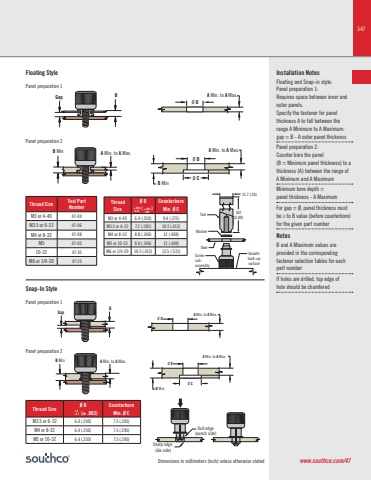
547Dimensions in millimeters (inch) unless otherwise statedInstallation Notes Floating and Snap-in style:Panel preparation 1:Requires space between inner and outer panels.Specify the fastener for panel thickness A to fall between the range A Minimum to A Maximum:gap = B - A outer panel thicknessPanel preparation 2: Counter bore the panel (B = Minimum panel thickness) to a thickness (A) between the range of A Minimum and A MaximumMinimum bore depth = panel thickness - A Maximum For gap = Ø, panel thickness must be ≥ to B value (before counterbore) for the given part numberNotesB and A Maximum values are provided in the corresponding fastener selection tables for each part number If holes are drilled, top edge of hole should be chamferedØ DØ DØ CA Min. to A Max.A Min. to A Max.B MinB GapB Min A Min. to A Max.12.7 (.50)102(4.00)WasherDoorScrewsubassemblySmoothback-upsurfaceToolBGapB Min A Min. to A Max.Ø DØ CØ DA Min. to A Max.A Min. to A Max.B Min.Dull edge(punch side)Sharp edge (die side)Thread Size Tool Part NumberM3 or 4-40 47-04M3.5 or 6-32 47-06M4 or 8-32 47-08M5 47-0510-32 47-10M6 or 1/4-20 47-25Floating StyleSnap-In StylePanel preparation 1Panel preparation 1Panel preparation 2Panel preparation 2www.southco.com/47 Thread SizeØ D ( )CounterboreMin. Ø CM3 or 4-40 6.4 (.250) 9.4 (.375)M3.5 or 6-32 7.2 (.283) 10.5 (.413)M4 or 8-32 8.8 (.346) 12 (.469)M5 or 10-32 8.8 (.346) 12 (.469)M6 or 1/4-20 10.5 (.413) 13.5 (.531)+.008-0.03 +.003-.001Thread Size Ø D (± .002)CounterboreMin. Ø CM3.5 or 6-32 6.4 (.250) 7.5 (.295)M4 or 8-32 6.4 (.250) 7.5 (.295)M5 or 10-32 6.4 (.250) 7.5 (.295)+0-0.1
